目次
In this blog, you can easily understand the evolution of IEEE802.11 wireless LAN series. It also discusses basic knowledge about Wi-Fi6, the latest IEEE 802.11ax standard[1].
◆The evolution of IEEE 802.11 wireless LAN series
Figure 1 shows the evolution of IEEE802.11 wireless LAN series from the viewpoint of the relationship between one wireless LAN access point (AP) and multiple client terminals. As shown in Fig.1 (a), since IEEE802.11 in 1997 until 11acWave1 in 2013, the only single client terminal transmission was allowed on the same frequency channel(CH#-X) at different times in uplink(UL) or downlink(DL). In 11acWave2 in 2013, as shown in Fig.1(b), in DL, a wireless transmission was simultaneously allowed to multiple client terminals (multi-users) on the same frequency channel by the technology of downlink multi-user MIMO (DL-MU-MIMO).
From 11ax in 2020, as shown in Fig.1(c), the wireless transmissions between one AP and multiple client terminals (multi-users) are going to be simultaneously allowed to in DL or UL on the same frequency channel by the technology of MU-MIMO or OFDMA. In particular, uplink multi-user (UL-MU) transmission technology using MU-MIMO or OFDMA is an important technology in 11ax.
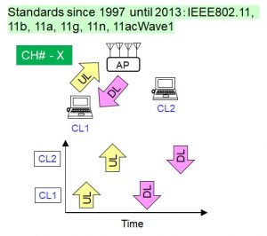
(a) Standards since 1997 until 2013
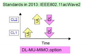
(b) Standards in 2013
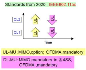
(c) Standards from 2020
Figure1 Evolution of IEEE802.11 wireless LAN series
◆Uplink multi-user (UL-MU) transmission in 11ax
Figure2 shows an example of UL-MU transmission by three client terminals. One AP and the three client terminals use a frequency of channel number X. The vertical axis represents the uplink signal power of each client terminal received at the AP, and the name of each client terminal is on the horizontal axis. In UL-MU transmission, although a transmission signal of a client terminal is attenuated by passing through propagation paths and received by the AP, a transmission power, an antenna gain, and a propagation attenuation amount are different for each client terminal. Therefore, as shown in Fig.2, a difference occurs in the received power of each client terminal’s signal at the AP. The demodulation and decoding characteristics of the signal with small received power may be degraded by the differences, which may make it difficult to perform reliable and stable communication.

Figure2 Example of UL-MU transmission by three client terminals
To operate UL-MU transmission properly in 11ax wireless LAN, each signal power received from client terminals at the AP should be equal. Therefore, as shown in Figure 3, each client terminal performs Transmission Power Control (TPC) to reduce each transmission power[2].
◆Transmission Power Control (TPC) at client terminals in UL-MU transmission
Fig.3 shows the example of UL-MU transmission by two client terminals with reduced transmission power and one normal client terminal. CL1 reduces its transmission power by Δ1 to make the received power of the CL1 signal at the AP equal to Target RSSI, which is the received power of the CL3 signal at the AP. The target RSSI is the signal power that all client terminals received by the AP have to reference to perform TPC properly in UL-MU transmission. CL2 reduces its transmission power by Δ2 to make the received power of the CL2 signal at the AP equal to the Target RSSI, too.
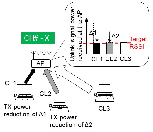
Figure3 Example of UL-MU transmission by two client terminals with reduced transmission power and one normal client terminal
However, in the first place, I have heard that in the 11ax Draft 3.0 version, there is no provision on how to set Target RSSI, so the setting method depends on the implementation[2]. Moreover, when client terminals perform TPC using UL-MU transmission in a wireless LAN in an indoor office environment, it is not clear how much and how often each transmission power at the client terminals is reduced.
Therefore, by using our wireless LAN of the indoor office environment with operating 11ac, I conducted an experimental study to obtain basic knowledge to contribute to performing TPC with UL-MU transmission properly. The basic knowledge will help to estimate and to determine the specification to perform TPC at the client terminal using UL-MU transmission.
◆Basic knowledge for UL-MU transmission led by my data analysis
I analyzed data of the uplink signal power of client terminals received by one AP(Cisco AP3802I ) with operating 11ac and found out statistical features in the data. A measurement period of the data was three months and I analyzed 70 data sets. The data analysis result is shown in Figure4.
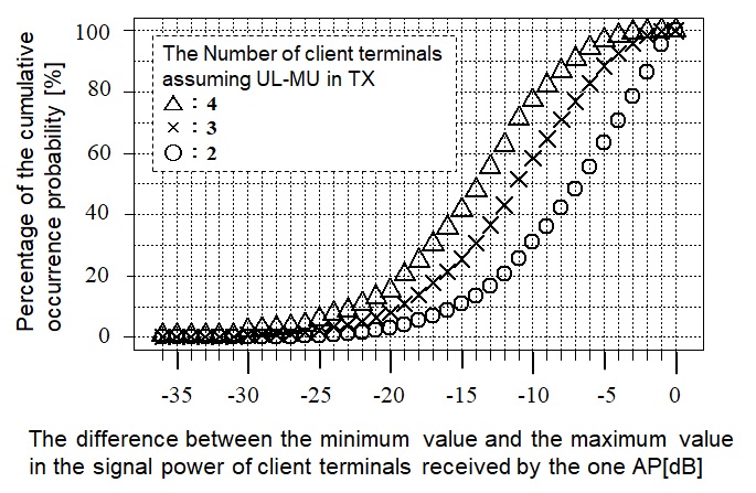
Figure4 Data analysis result
Fig.4 shows the cumulative occurrence probability of the difference between the minimum value and the maximum value in the signal power of client terminals received by the one AP. In Fig.4, the assumed number of client terminals simultaneously transmitted as UL-MU transmission means two by an open circle, three by a cross, and four by an open triangle. The horizontal axis represents the difference between the minimum value and the maximum value in the signal power of client terminals received by the one AP. For example, if three client terminals are assumed as UL-MU transmission as shown in Fig.3, the horizontal axis represents Δ1 shown in Fig.3. The vertical axis represents the percentage of the cumulative occurrence probability.
The wireless LAN module built into my PC is Intel Dual Band Wireless-AC 7265 for IEEE802.11ac Wave1, which has 5 levels of transmission power in the 5 GHz band. When the signal power of the wireless LAN module received by the AP was measured, the maximum value of the variable range of the transmission power in the 5 levels was 7 dB. Figure5 is the same figure as Fig.4, focusing on -7 dB on the horizontal axis.
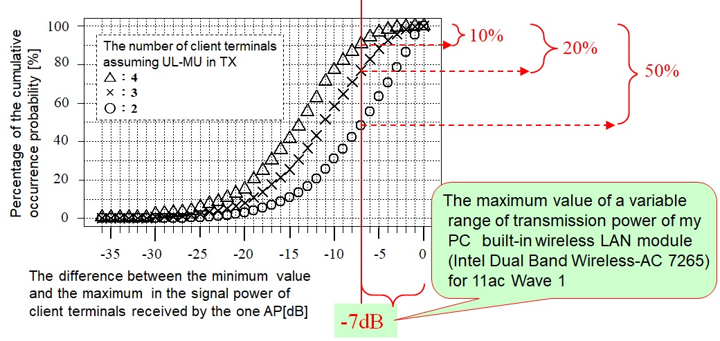
Figure5 Data analysis result focusing on -7 dB on the horizontal axis
For example, we assume that the specification of the maximum range for reducing transmission power at the client terminal compatible with 11ax UL-MU transmission is 7 dB and we focus on -7 dB or more of the horizontal axis in Fig.5. According to Fig.5, when the number of client terminals assuming simultaneous transmission of UL-MU transmission is two, the probability that the uplink signal power of each client terminal received at the AP can be equalized in the range of 7dB is 50% or less. Similarly, when the number of client terminals assuming simultaneous transmission of UL-MU transmission is three, the probability that the uplink signal power of each client terminal received at the AP can be equalized in the range of 7dB is 20% or less. Similarly, when the number of client terminals assuming simultaneous transmission of UL-MU transmission is four, the probability that the uplink signal power of each client terminal received at the AP can be equalized in the range of 7dB is 10% or less.
As a test result, I noticed that in order to properly operate UL-MU transmission with 11ax wireless LAN, the maximum range of 7dB for reducing transmission power at the client terminal seems to be small.
I believe firmly that wireless terminal manufacturers will have a good collaboration with Cisco to have a good performance for UL-MU transmission in Wi-Fi6.
◆References
[1] Cisco systems, “Technical white paper IEEE 802.11ax: The Sixth Generation of Wi-Fi”,
https://www.cisco.com/c/dam/en/us/products/collateral/wireless/white-paper-c11-740788.pdf (accessed 2019-12-17).
[2] Land Radio Communication Committee, Information and Communication Technology Subcommittee, Information and Communications Council, Ministry of Internal Affairs and Communications, JAPAN, “Doc.48-2-2: Draft version report on technical requirements for next-generation high-efficiency wireless LAN”, https://www.soumu.go.jp/main_content/000614204.pdf, http://www.soumu.go.jp/main_sosiki/joho_tsusin/policyreports/joho_tsusin/ido/02kiban12_04000249.html,April 11, 2019 (in Japanese), (accessed 2019-12-17).
◆About the author
Takashi Matsudo is a Senior Expert of a wireless LAN technology in Applied Technology Engineering Department1 at NetOneSystems Co., Ltd. and has evaluated Cisco’s wireless LAN products since 2001. His fields of expertise are a radio wave propagation and an antenna technology. He and his colleagues received awards four times(in 2013, 2014, 2015 and 2018) in Cisco Technology Contest held by Cisco Japan(Cisco Systems G.K.). He has a license of First-Class Technical Radio Operator.
※本記事の内容は執筆者個人の見解であり、所属する組織の見解を代表するものではありません。